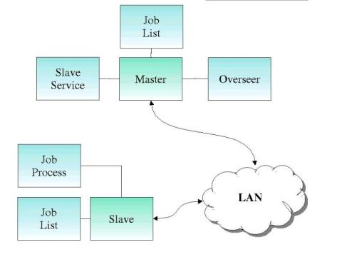
Figure 4 - System Overview
This section goes into detail of the actual design of the project. The project was mapped around the analogy of a master and the many slaves that he/she owned. Masters have an overseer that keeps track of the slaves and assign work to them. All slaves that worked for the master would report to the overseer each time the task they were assigned was completed. This simple analogy lent itself very nicely to the setup of the various objects, master, overseer and slaves. The next sections will go more deeply into the various design choices made with the reasoning behind them, system architecture and discussion of the individual elements.
The design of DGCC took various twist and turns as the project developed from initial idea to the present system state. A server that is developed today without threading will not scale or handle the demand of many users. So in designing the two servers, master and slave, the issue of threading was considered. Initially it was thought that the master and the slave both would be multithreaded. This poised problems in regards to concurrency when using semaphores. Since ORBacus provides concurrency naturally the master was changed from a multithreaded server to a single operating thread. CORBA and more particularly ORBacus provide a thread system that handles request either from a thread pool, thread-per-request, or thread-per-client. Using these natural characteristics of CORBA the server, for now, can be simplified greatly by making it work with a single execution path.
The slave on the other hand is threaded with one thread, the job process thread. The idea was that a thread will be issue for each job that needs to be done. As the project developed it was discovered that a thread should only be created and used for each Central Processing Unit (CPU) the participating system contains. With this in mind the slave used the abilities of Java Like Threads for creating a blocking semaphore on the job list. If a thread does not find work it waits and continues as work. This will be discussed further below in Section 4.4.3.1 Job Process.
The resulting design is a simple and elegant solution to problem of distributing a compilation process. As seen in the figure below, there is very little to what makes up DGCC. The structure of the project is very generic that it can be applied to any distributed problem. In the rest of the chapter a brief description of what makes up the design and how it operates in action. Figure 4 is a diagram of what the master and slave interacting through a local area network.

Figure 4 - System Overview
The following diagrams show the interaction that occurs between the master and the slave.
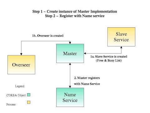
Figure 5 covers the process of what happens when the master starts up to compile a project. It first creates the Overseer and Slave service. It then registers itself with the Name Service for slaves to find it later. The master then reads in the Makefile from the present working directory that was given to it by the user. Finally it adds all these jobs into the Job List.

Figure 5 - Master Startup
4.3.2 Slave Startup & Registration With Master
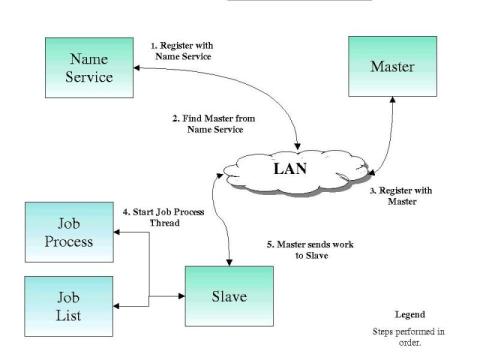
The process of the slave starting up is described in Figure 6 below. The slave will register itself with the Name Service and find the location of the master. After this the slave registers itself with the master. The slave will start a job process thread for handling all requests from the master. The final step is that master will start sending jobs to theslave.

Figure 6 - Slave Startup & Registration
4.4.3 Interaction between the Master and Slave
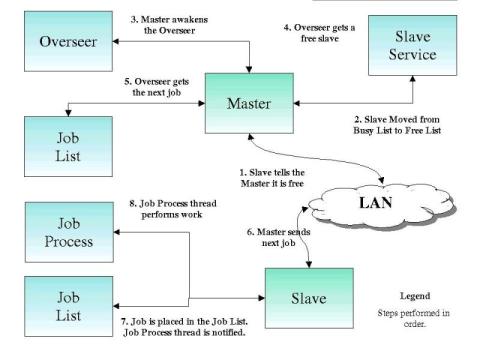
This next diagram, Figure 7, explains what happens when the slave is finished with a job sent from the Master. The slave notifies the master that it is free for the next job. The master moves the slave from the busy list to the free list. The overseer is awakened to deal with this slave. The overseer grabs the next job and the next free slave and sends the job to the free slave. This newly chosen free slave adds the job to its job list and notifies the job process threads. The Job process thread performs the work and the cycle starts again.

Figure 7 - Master & Slave Interaction
| Previous: Chapter 3 - Other Technologies | Home | Next: Chapter 4 - System Components |